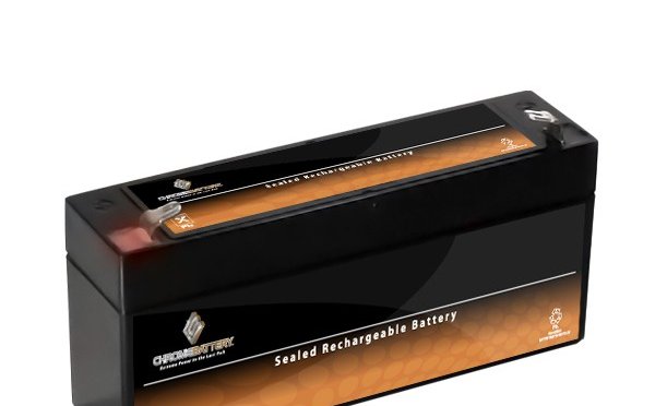
This article is going to cover the different methods of charging a sealed lead acid (SLA) battery. This type of battery is generally designed with a low-level over-voltage potential to restrict it from attaining its gas generating potential while under charge. Excessive charging may cause gas production, venting, water depletion and dry-out. To prevent excessive charging, chargers have an inbuilt circuit to detect when a battery is fully charged.
Before beginning to charge an SLA battery, we need to know what voltage it should be charged at. This voltage is referred to as ‘Float Voltage’. This is required to keep the battery charging till it is needed. Float voltage depends on battery type and its room temperature. Typically, for a lead-acid battery, the float voltage has to be maintained at 2.25 Volts per cell. Hence, for a typical battery of 6 cells, float voltage should be set around 13.5 Volts (or 13.8 Volts). Also, the current should be set less than 1 Amp.
CC, CV stand for ‘Constant Current’ and ‘Constant Voltage’ respectively. In this charging method, a regulated current raises the battery voltage until the higher voltage charge limit is attained. At this point, the current drops because saturation occurs. The charger design for this type has two potentiometers connected. One for changing current limit and another one for changing the voltage limit.
Consider a 12 Volt SLA battery in its discharged state of 12 Volts with maximum float voltage of 14 Volts. When it is connected to a power supply, it will begin charging at a constant current level (set using the potentiometer responsible for current). The current will remain constant until the voltage reaches 14 Volts limit. At this point, the charger will change into constant voltage mode and the current will gradually decrease to zero until the battery is fully charged. The charge time is usually up to 12 hours for smaller batteries.
Representative graph for CC/CV charger (Note: Not for scaling purpose)
Basic circuit representation of a 3 Pot CC/CV charger circuit (Circuit taken from Source )
PWM stands for ‘Pulse Width Modulation’. The main aim of this type of charger is to apply a large amount of current into a battery at periodic time interval with a specific pulse width. This reduces the damage caused to the battery and increases efficiency. Additionally, this charger senses voltage drops in the battery and sends pulses of very short charging cycles. This may occur several hundred times in a minute. It is referred to as "pulse width" because the width of the pulse varies a lot, ranging from a few microseconds to several seconds. This helps in keeping an already charged battery from discharging.
This method can be combined with constant current (CC), constant voltage (CV) or CC/CV to obtain the desired combined charging technique.
Basic circuit representation of a PWM based charge controller for a 12V battery(Circuit taken from Source )
Graph representation of a PWM based charging (Note: Not for scaling purpose)
MPPT stands for Maximum Power Point Tracking. It is basically a high-frequency DC-DC converter. Before understanding what MPPT is, we need to understand why it is required.
Chargers based on this technology are generally used with solar panels. The reason behind this is that the solar panels have a fluctuating output and not a fixed one i.e. the current and voltage output of solar panel changes as per the physical conditions irrespective of the rated watts. During warm days or hot conditions, there are significant power drops as panel temperature goes up, whereas during cold days the power output increases. Also, a normal solar panel will have a much higher rated voltage and current(7.39 A at 17.6V for 130 W) compared to a 12V SLA battery. This will again lead to power losses. To counter these issues, we bring MPPT based controller into play.
This high-frequency DC-DC converter takes DC input from solar panels and changes it to high-frequency AC. Next, it is converted back into a different DC voltage and current to make it ideal for the battery. This creates a match in between the panels and the battery. The reason for it being high frequency is to make sure that it can be designed with high-efficiency transformers and other circuit components. But high frequency invites noise which is tackled using noise isolation circuits.
Maximum Power Point Tracking is a digital tracking method where the controller senses the output of the panels and compares it to the battery voltage. It then decides what will be the ideal power input for the battery to charge with least losses. The sensed output of the panel is converted into a voltage that can send maximum current into the battery. This maximum power point varies as per the conditions. So the job of MPPT based charge controller is to track down this point at all times and adjust the output to battery accordingly.
Basic circuit representation of an MPPT charge controller(Circuit by John Clarke Source )
The general graph looks like this. Here the max point is rated at 100W (red curve) (Note: Graph for representative purpose only. Not for scaling)
CC/CV based |
PWM based |
MPPT based |
|
|
|
MPPT chargers even though expensive compared to other chargers, are the best choice owing to their ability to adjust according to the input supply and availing least power losses.
So if you are looking to charge a normal SLA battery with a fixed input, then it would be a much wise option to go for CC/CV chargers because of their inexpensive setup. But if the application requires more power optimization then straightaway opt for MPPT. The initial investment will be more but it will save you a lot in the long run.