This demo, along with external sources, takes us through the step by step instructions to set-up, initialize, and make a working Internet of Thing (IoT) device. The platform for ESP32 is based on Espressif IoT Development Framework (esp-idf), which is the official development framework for the ESP32 chip. For further development or for reference, the source code used for the demo is being attached along with this tutorial. The server side of things are handled by SwarmSense. We will go through the step by step instructions to set-up the device in SwarmSense, as well.
SETTING UP THE ENVIRONMENT
ESP-IDF
The best guide for ESP-IDF would be its developers’ words. Thus, I would like to point you to that direction. Please refer this github for the ESP-IDF source code and installation instructions. Probably, I will make another detailed tutorial regarding this, in the future.
Visual Code Studio
Installing Visual Code Studio is simple and straight forward. Go to the official home page of Visual Code Studio, download the package for windows, install the software by running the installer and following the instructions on screeen. Make sure you enable the right click on Windows folder and open with Visual Studio Code option at the end as it can come in handy. We have been working on Visual Code Studio for editing the code but you are free to use any editor for the same. A simple text editor like notepad will also be sufficient for this job.
ESP-IDF
Let us set-up ESP-IDF
- Get the latest code: esp32-idf-mqtt
- Extract it to a custom folder (preferably a path without space in its name).
- Open the folder in a source code editor. Go to main/header.h file. We need to do two tasks here,
Change the WIFI_SSID and WIFI_PASSWORD values.
[code]
#define WIFI_SSID "my_wifi_ssid"
#define WIFI_PASSWORD "my_wifi_password"
[/code]
Change the SENSOR_ID and SENSOR_KEY values.
[code]
#define SENSOR_ID "my_sensor_id"
#define SENSOR_KEY "my_sensor_key"
[/code]
- We have done all the basic settings for the project. Save the above configuration. Now, let's burn the code. The command to compile and burn the code is:
make flash
- You maybe wondering why I'm still talking. I would like to introduce you to another command too. This helps us to monitor the working of ESP32. It is a serial console. The command is:
make monitor
- We can do both the steps in 8 and 9 with a single command, like the stroke of a wand. The command is:
make flash monitor
- Go to the dashboard that we have created in SwarmSense. Turn the knob of the potentiometer and see the change in values of the gauge that we have created. We can turn the LED on and off from the console itself.
SWARMSENSE
SwarmSense is a fully equipped and self hosted IoT platform. With SwarmSense you can monitor any type of time-series data. Server metrics are also a time-series data so it is very easy to monitor your server stats with SwarmSense.
We’ll have a step wise approach on how to make a sensor in SwarmSense, how to display the values and how to make a dashboard to view and control the devices in one window. There are several documents regarding SwarmSense and the different utilities associated with it, which are being continuously updated and posted, but here, we will be dealing with the basic things to make our device work.
- Create a company
- Create a sensor
- Check the setup
- Create a dashboard
1. Create a company
For a better organised structure, it is good to start a company. Click onto the Companies tab on the left. Follow the images to create a new company.


2. Create a sensor
Each device is a sensor in SwarmSense. So we need to create a sensor for each device we have in our list.

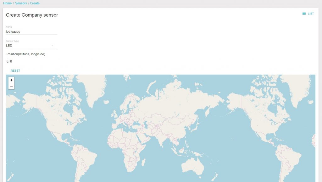
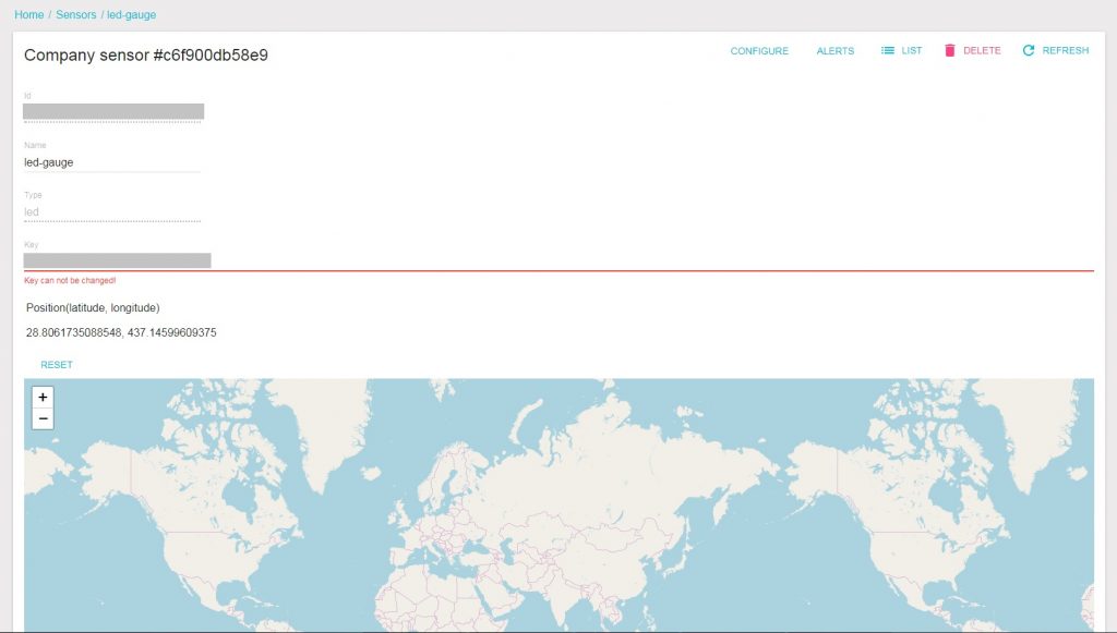

We need the values id and the key. This information has to be burned into the firmware to enable the sensor to push information to the server, to the designated destination.
3. Check the setup
We have a (supposedly) working hardware and the minimum software required to view the values send by the hardware. Let’s try and run the hardware to check if the whole system is working. Power up the transmitter and change the value of the potentiometer. A new value should be send to the server, if everything is working right. This value can be seen represented as a graph, in the dashboard section of the SwarmSense.
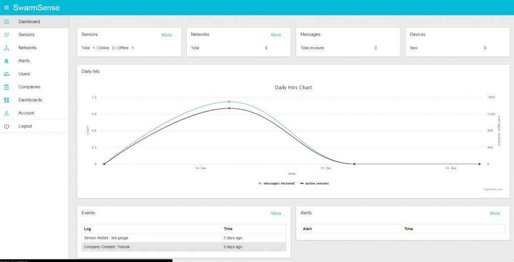
These values can be viewed as a graph.

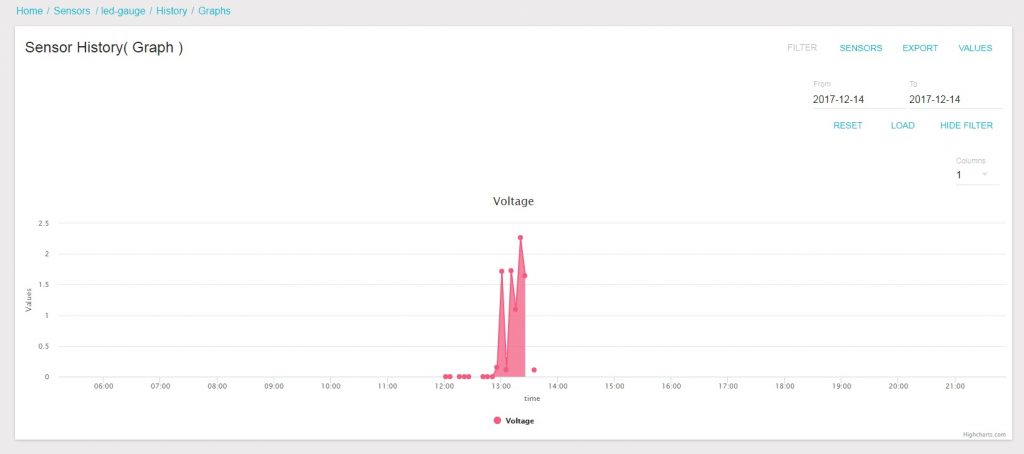
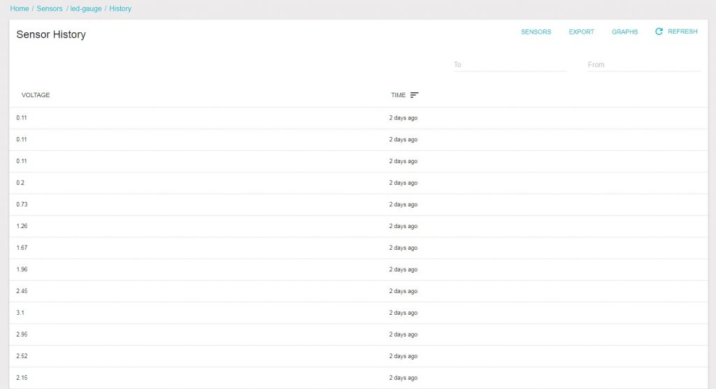
These can be viewed as a list too.
4. Create a dashboard
Now, wouldn’t it be good to have a better graphical interaface to the data that we have send just now? This is one of the best parts of SwarmSense. Let’s represent the data in a better view with dashboards. Dashboard can live update a value received by the server on the webpage, the current state of the device and the value which we need to send to the device. Let us make a dashboard.


There you go, the dashboard is ready. Now let’s see how to represent the data that we are sending. Let’s edit it and create a new widget.


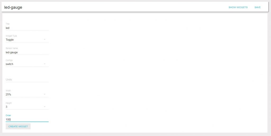

Now a widget with a control interface for an LED is made. Let’s make another widget to display the values send by the potentiometer too.

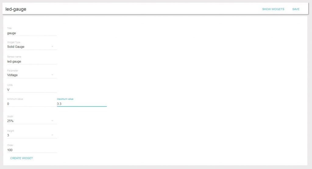

Tada.!! Both the widgets are created. Now the values that you send from your device are updated in the dashboard. Check it yourself and have fun.
This tutorial gives an insight into how ESP32 and SwarmSense can be used to control and monitor an IoT device. This example can be extrapolated to most of the IoT devices that are in the market. It shows how a data from a remote device can be brought into the server for monitoring and how a data can be send from a server to a remote device to do a predefined functionality.
Wanna make your home smart? Wanna remotely control appliances and monitor your home? The canvas is plain and the colours are ready… paint your imagination.
Downloads:
- ESP32 Code: esp32-idf-mqtt

